These are the ramblings of Matthijs Kooijman, concerning the software he hacks on, hobbies he has and occasionally his personal life.
Most content on this site is licensed under the WTFPL, version 2 (details).
Questions? Praise? Blame? Feel free to contact me.
My old blog (pre-2006) is also still available.
See also my Mastodon page.
| Sun | Mon | Tue | Wed | Thu | Fri | Sat |
|---|---|---|---|---|---|---|
| 1 | 2 | 3 | ||||
| 4 | 5 | 6 | 7 | 8 | 9 | 10 |
| 11 | 12 | 13 | 14 | 15 | 16 | 17 |
| 18 | 19 | 20 | 21 | 22 | 23 | 24 |
| 25 | 26 | 27 | 28 | 29 | 30 | 31 |
(...), Arduino, AVR, BaRef, Blosxom, Book, Busy, C++, Charity, Debian, Electronics, Examination, Firefox, Flash, Framework, FreeBSD, Gnome, Hardware, Inter-Actief, IRC, JTAG, LARP, Layout, Linux, Madness, Mail, Math, MS-1013, Mutt, Nerd, Notebook, Optimization, Personal, Plugins, Protocol, QEMU, Random, Rant, Repair, S270, Sailing, Samba, Sanquin, Script, Sleep, Software, SSH, Study, Supermicro, Symbols, Tika, Travel, Trivia, USB, Windows, Work, X201, Xanthe, XBee
 &
&
(With plugins: config, extensionless, hide, tagging, Markdown, macros, breadcrumbs, calendar, directorybrowse, entries_index, feedback, flavourdir, include, interpolate_fancy, listplugins, menu, pagetype, preview, seemore, storynum, storytitle, writeback_recent, moreentries)
Valid XHTML 1.0 Strict & CSS
For a theatre performance, I needed to make the tail lights of an old car controllable through the DMX protocol, which the most used protocol used to control stage lighting. Since these are just small incandescent lightbulbs running on 12V, I essentially needed a DMX-controllable 12V dimmer. I knew that there existed ready-made modules for this to control LED-strips, which also run at 12V, so I went ahead and tried using one of those for my tail lights instead.
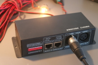
I looked around ebay for a module to use, and found this one. It seems the same design is available from dozens of different vendors on ebay, so that's probably clones, or a single manufacturer supplying each.
DMX module details
This module has a DMX input and output using XLR or a modular connector, and screw terminals for 12V power input, 4 output channels and one common connection. The common connection is 12V, so the output channels sink current (e.g. "Common anode"), which is relevant for LEDs. For incandescent bulbs, current can flow either way, so this does not really matter.
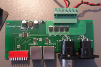
Opening up the module, it seems fairly simple. There's a microcontroller (or dedicated DMX decoder chip? I couldn't find a datasheet) inside, along with two RS-422 transceivers for DMX, four AP60T03GH MOSFETS for driving the channels, and one linear regulator to generate a logic supply voltage.
On the DMX side, this means that the module has a separate input and output signals (instead of just connecting them together). It also means that the DMX signal is not isolated, which violates the recommendations of the DMX specification AFAIU (and might be problematic if there is more than a few volts of ground difference). On the output side, it seems there are just MOSFETs to toggle the output, without any additional protection.
Just try it?
I tried connecting my tail lights to the module, which worked right away, nicely dimming the lights. However:
When changing the level, a high-pitched whine would be audible, which would fall silent when the output level was steady. I was not sure whether this came from the module or the (external) power supply, but in either case this suggests some oscillations that might be harmful for the equipment (and the whine was slightly annoying as well).
Dimming LEDs usually works using PWM, which very quickly switches the LED on and off, faster than the eye can see. However, when switching an inductive load (such as a coil), a very high voltage spike can occur, when the coil current wants to continue flowing, but is blocked by the PWM transistor.
I'm not sure how much inductance a normal light bulb gives, but there will be at least a bit of it, also from the wiring. Hence, I wanted to check the voltages involved using a scope, to prevent damage to the components.
Measuring
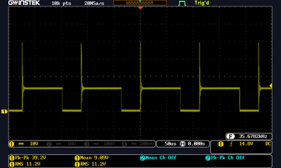
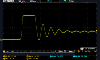
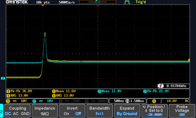
Looking at a channel output pin on a scope shows the following. The left nicely shows the PWM waveform, but also shows a high voltage pulse when the transistor is switched off (remember that the common pin is connected to 12V, so when the transistor pin is on, it sinks current and pulls the channel pin to 0V, and when it is off, current stops flowing and the pin returns to 12V). The right image shows a close-up of the high-voltage spike.
The spike is about 39V, which exceeds the maximum rating of the transistor (30V), so that is problematic. While I was doing additional testing, I also let some of the magic smoke escape (I couldn't see where exactly, probably the cap or series resistor near the regulator). I'm not sure if this was actually caused by these spikes, or I messed up something in my testing, but fortunately the module still seems to work, so there must be some smoke left inside...
The shape of this pulse is interesting, it seems as if something is capping it at 39V. I suspect this might be the MOSFET body diode that has a reverse breakdown. I'm not entirely sure if this is a problematic condition, the datasheet does not specify any ratings for it (so I suspect it is).
Adding diodes
Normally, these inductive spikes are fixed by adding a snubber diode diode. I tried using a simple 1N4001 diode, which helped somewhat, but still left part of the pulse. Using the more common 1N4148 diode helped, but it cannot handle the full current (though specs are a bit unclear when short but repetitive current surges are involved).
I had the impression that the 1N4001 diode needed too much time to turn on, so I ordered some Schottky diodes (which should be faster). I could not find any definitive info on whether this should really be needed (some say regular diodes already have turn-on times of a few ns), but it does seem using Schottkys helped.
The dimmer module supports 8A of current per channel, so I ordered some Schottkys that could handle 8A of current. Since they were huge, I settled for using 1N5819 Schottkys instead. These are only rated for 1A of current, but that is continuous average current. Since these spikes are very short, it should be able to handle higher currents during the spikes (it has a surge current rating of 25A, but that is only non-repetitive, which I'm not sure applies here...).
Here's what happens when adding a 1N5819:
The yellow line is the channel output, the blue line is the 12V input. As you can see, the pulse is greatly reduced in duration. However, there is still a bit of a spike left. Presumably because the diode now connects to the 12V line, the 12V line also follows this spike. To fix that, I added a capacitor between 12V and GND. I would expect that any input capacitors on the regulator would already handle this, but it seems there is a 330Ω series resistor in the 12V line to the regulator (perhaps to protect the regulator from voltage spikes)?
Adding a capacitor
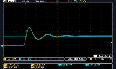
This is what happens when adding a 100nF ceramic capacitor (along with the 1N5819 diode already present):
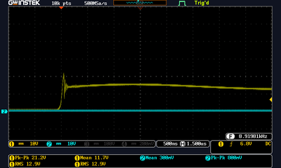
This succesfully reduces the pulse voltage, but introduces some ringing (probably resonance between the capacitance and the inductance?). Replacing with a 1uF helps slightly:
Note that I forgot to attach the blue probe here. The ringing is still present, but is now much lower in frequency. In this setup, the high-pitched whining I mentinoed before was continuously present, not just when changing the dim level.
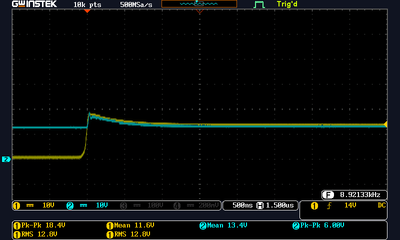
I also tried using a 1uF electrolytic capacitor, which seems to give the best results, so I stuck to that. Here's what my final setup gives:
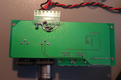
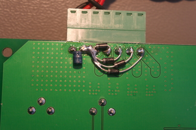
I soldered in these diodes and the cap on the bottom side of the PCB, since that's where I could access the relevant pins:
Unsolved questions
I also tested with a short LED strip, which to my surprise showed similar surges. They were a lot smaller, but the current was also a lot smaller. This might suggest that it's not the bulb itself that causes the inductive spike, but rather the wiring (even though that was only some 20-30cm) or perhaps the power supply? It also suggests that using this with a bigger LED strip, you might actually also be operating the MOSFETs outside of their specifications...
I'm also a bit surprised that I needed the capacitor on the input voltage. I wonder if there might also be some inductance on the power supply side (e.g. the power supply giving a voltage spike when the current drops)?
Finally, wat causes this difference between the electrolytic and ceramic capacitors? I know they are different, but I do not know off-hand how exactly.
Got any insights? Feel free to leave a comment or drop me a mail!

Comments are closed for this story.